(For Dave, Abbs and the Andys)
Here we go, an example of a program in G-code to make some of the Brass Bushes I’ve been making this week (along with an explanation of what each line does) Sometimes it’s easier to read a program using map grid reading methodology (draw it up on graph paper like our works notepads) if spatial thinking isn’t a strong point. Comment lines are in Red and are not seen by the machine as instructions but the user can still see them. My extra comments are in Purple. I haven’t linked this on the main site as yet as somebody is bound to try it out, get it wrong and bend something expensive.
:0701(TOP HAT BUSHES) (0701 Program number, (Top Hat Bushes) description of the job.
M98P1 (M98 calls a sub program, P1 is the program number)
N1 T0101 M08(RGH TURN CNMG) N1 is a line number, T0101 is tool 01,offset 01, M08 turns on the coolant.
G96 S180 M03 G96 sets the spindle in surface speed mode, S180 is the spindle speed in Meters per min, M03 starts the spindle clockwise
G50 S1800 G50 sets a spindle max speed limit, S1800 is the max speed in RPM
G00 X40.0 Z30.0 G00 sets rapid movement, X40.0 is the diameter position, Z30.0 is the distance in the length position.
G01 Z0.0 F5.0 G01 sets a feed mode, Z0.0 is the position to go to, F5.0 is the movement in MM per revolution.
G01 X-1.0 F0.25 G01 sets feed rate mode, X-1.0 cuts past the middle of the diameter to remove any pip, F0.25 is the feed per revolution.
G00 X40.0 Z1.0 G00 sets rapid movement, X40.0 & Z1.0 being on the same line moves both axis at the same time
G71 U2.0 R0.5 G71 is a diameter turning, canned cycle, U2.0 is the depth of cut in the X axis, R0.5 is how much the tool retracts in the X axis when it reaches the final point in Z on each pass.
G71 P100 Q200 U0.25 W0.15 F0.28 G71 is the second instruction of the canned cycle, P100 is the start of the shape it has to cut, Q200 is the end of the shape it has to cut, U0.25 is the finishing allowance in the X axis, W0.15 is the finishing allowance in the Z axis, F0.28 is the feed rate for all following moves in the canned cycle.
N100 G00 X23.0 N100 is the first line number of the shape, G00 sets rapid movement mode,X23.0 is the position the axis moves to.
G01 Z0.0 G01 sets feed rate movement,Z0.0 is the position it moves to (the zero point of the job so the tool is touching and not touching at the same time.
G01 X25.0 Z-1.0 G01 sets feed rate movement, X25.0 and Z-1.0 moves both axis to create and 1mm chamfer.
G01 Z-25.0 G01 sets feed rate movement. Z-25.0 moves the Z axis only to cut from right towards the chuck by 25.0mm
G01 X33.0 G01 sets feed rate movement, X33.0 moves the X axis only to the 33.0mm diameter position.
G01 X35.0 Z-26.0 G01 sets a feed rate movement, X35.0 Z-26.0 creates another corner chamfer of 1mm.
G01 Z-33.0 G01 sets a feed rate movement, Z-33.0 cuts from right to left to a Z position of -33.0mm.
N200 G01 X39.9 N200 tells the machine this is the last set of co-ordinates that define the required shape,G01 sets a feed rate movement, X39.9 is the finishing point of that movement.
G70 P100 Q200 F0.1 G70 commands the machine to carry out a finishing cycle, P100 defines the start line of the shape, Q200 defines the final line of the shape, F0.1 sets the feed rate of the finishing cycle.
M98 P1 M09 M98 calls a sub program, P1 is the sub program being called, M09 turns off the coolant.
M05 M05 turns off the spindle.
M01 M01 if the optional stop button is selected will pause the program at this point until the cycle start is pressed again, if Optional stop is not enabled it will be ignored.
N2 T0303 M08(CENTRE DRILL) N2 is the line number, T0303 calls tool 03 offset 03 and indexes the turret, M08 switches on the coolant, CENTRE DRILL describes the process.
G96 S180 M03 G96 sets spindle speed in meters per minute, S180 is the max speed used, M03 starts the spindle in a clockwise direction.
G50 S1800 G50 sets a spindle speed limit command, S1800 is the maximum speed the spindle can reach in revolutions per minute.
G00 X0.0 Z3.0 G00 sets rapid movement, X0.0 is the centre of the bar, Z3.0 is 3mm away from the end of the bar.
G01 Z-4.0 F0.2 G01 sets feed rate movement, Z-4.0 is the finishing point of the Z move, F0.2 is the feed rate in MM per revolution of the chuck.
G00 Z25.0 G00 sets rapid rate movement, Z25.0 is the axis that moves.
M98P1 M98 calls a sub program, P1 is the sub program called.
M05 M05 stops the spindle.
M00 M00 is a pause command, there is no option to ignore it, the machine will pause until cycle start is pressed again.
N3 T0505 M08(DRILL 19.5MM) N3 is a line number, T0505 selects tool 05 offset 05, M08 turns on the coolant, DRILL 19.5mm is a description of the tool being used.
G96 S100 M03 G96 sets spindle rotation to surface speed mode, S100 is the spindle speed maximum in meters per minute, M03 starts the spindle in a clockwise direction.
G50 S1000 G50 sets a spindle rotation speed limit in RPM, S1000 is the maximum spindle speed in RPM.
G00 X0.0 Z3.0 G00 sets rapid movement mode, X0.0 is the centre line of the workpiece, Z3.0 is 3mm away from the job face, both moves are carried out at the same time as both axis are used on the same line.
G01 Z1.0 F5.0 G01 sets feed rate movement, Z1.0 is the position the tool feeds to, F5.0 is the feed rate in MM per revolution.
G74 R1.0 G74 is a canned cycle for peck drilling, R1.0 is the amount the drill moves back on each “peck” usually called “Retract”.
G74 Z-33.0 Q5000 F0.06 G74 calls the second line of the peck drilling cycle, Z-33.0 is the direction and finished point of the drilling, Q5000 is the depth of each peck in Microns so this would be 5mm,F0.06 is the feed rate per revolution of the work piece.
G00 Z25.0 M09 G00 sets rapid mode movement, Z25.0 is the position to rapid move to, M09 turns off the coolant.
M98P1 M98 calls a sub program, P1 is the sub program called.
M05 M05 turns off the spindle.
M01 M01 if the optional stop button is selected will pause the program at this point until the cycle start is pressed again, if Optional stop is not enabled it will be ignored.
N4 T0707 M08(REAM 20MM) N4 is a line number, T0707 selects tool 07 offset 07, M08 turns on the coolant, REAM 20mm is a description of the tool being used.
G97 S350 M03 G97 sets the spindle into RPM mode, revolutions per minute, S350 is the spindle speed being commanded, M03 starts the spindle in a clockwise direction.
G00 X0.0 Z3.0 G00 sets for rapid mode movement, X0.0 is the centre line of the work piece, Z3.0 is 3mm away from the end of the workpiece.
G01 Z-30 F1.0 G01 sets feed rate move movement, Z-30.0 is the Z position to feed to, F0.1 is the feed rate per revolution of the chuck. Unlike drilling, this is one single fluid plunge of the reamer to it’s final depth.
G00 Z30.0 M09 G00 sets the axis to rapid mode movement, Z30.0 is the point the axis moves to, M09 turns off the coolant.
M98P1 M98 calls a sub program, P1 is the sub program called.
M05 M05 stops the spindle.
M00 M00 is a pause command, there is no option to ignore it, the machine will pause until cycle start is pressed again.
N5 T0909 M08(CHAMFER+PARTOFF 3MM TIP) N5 is a line number, T0909 selects tool 09 offset 09, M08 turns on the coolant, CHAMFER+PARTOFF 3MM TIP is a description of the tool being used.
G96 S180 M03 G96 sets spindle rotation to surface speed mode, S180 is the spindle speed maximum in meters per minute, M03 starts the spindle in a clockwise direction.
G50 S1200 G50 sets a spindle maximum RPM, S1200 is the maximum allowed RPM.
G00 X42.0 Z30.0 (These are all rapid or feed rate moves that will use a part off tool to cat a chamfer of 1mm at 45 degrees at the back end of the job, then continue down to cut the finished component from the main material.)
G01 Z2.0 F6.0 ( )
G01 Z-33.0 F4.0 ( )
G01 X36.0 F0.08 ( )
G00 X41.0 ( )
G00 Z-32.0 ( )
G01 X35.0 F0.1 ( )
G01 X33.0 Z-33.0 F0.03 ( )
G01 X18.0 F0.05 ( )
G00 X45.0 M09 ( )
G00 Z30.0 ( )
M98P1 M98 calls a sub program, P1 is the sub program called.
M30 M30 ends the program and rewinds to the first line of the program.
So at this point you have a machined , reamed and cut off brass bush sat in the tray of the machine all finished. All in a little under 2 minutes.
The program without my comments is displayed below.
:0701(TOP HAT BUSHES)
M98P1
N1 T0101 M08(RGH TURN CNMG)
G96 S180 M03
G50 S1800
G00 X40.0 Z30.0
G01 Z0.0 F5.0
G01 X-1.0 F0.25
G00 X40.0 Z1.0
G71 U2.0 R0.5
G71 P100 Q200 U0.25 W0.15 F0.28
N100 G00 X23.0
G01 Z0.0
G01 X25.0 Z-1.0
G01 Z-25.0
G01 X33.0
G01 X35.0 Z-26.0
G01 Z-33.0
N200 G01 X39.9
G70 P100 Q200 F0.1
M98 P1 M09
M05
M01
N2 T0303 M08(CENTRE DRILL)
G96 S180 M03.
G50 S1800
G00 X0.0 Z3.0
G01 Z-4.0 F0.2
G00 Z25.0
M98P1
M05
M00
N3 T0505 M08(DRILL 19.5MM)
G96 S100 M03
G50 S1000
G00 X0.0 Z3.0
G01 Z1.0 F5.0
G74 R1.0
G74 Z-33.0 Q5000 F0.06
G00 Z25.0 M09
M98P1
M05
M01
N4 T0707 M08(REAM 20MM)
G97 S350 M03
G00 X0.0 Z3.0
G01 Z-30 F1.0
G00 Z30.0 M09
M98P1
M05
M00
N5 T0909 M08(CHAMFER+PARTOFF 3MM TIP)
G96 S180 M03
G50 S1200
G00 X42.0 Z30.0
G01 Z2.0 F6.0
G01 Z-33.0 F4.0
G01 X36.0 F0.08
G00 X41.0
G00 Z-32.0
G01 X35.0 F0.1
G01 X33.0 Z-33.0 F0.03
G01 X18.0 F0.05
G00 X45.0 M09
G00 Z30.0
M98P1
M30
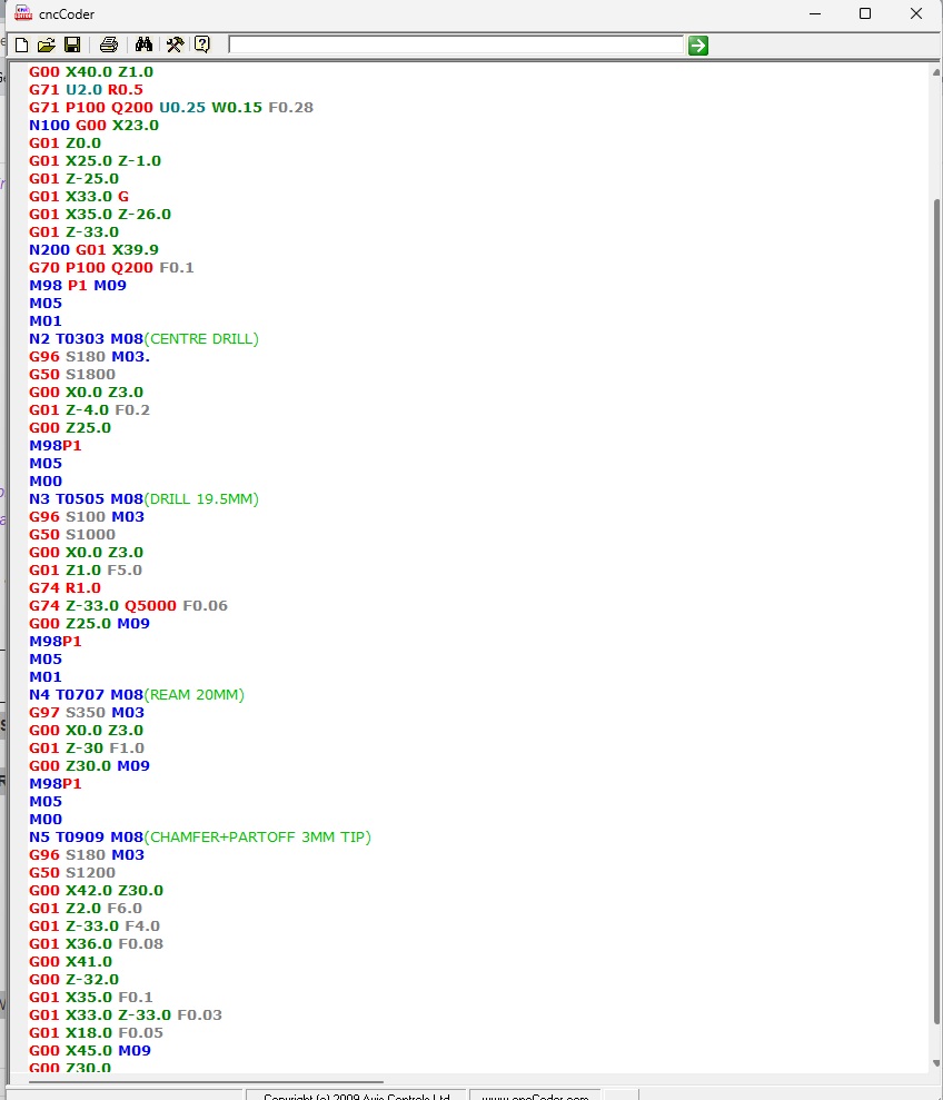
If you copy and paste this into CNCCoder it automatically highlights with different colours making the program easier to read as below.
From this point you simply unclamp the chuck (it’s hydraulic on a foot peddle) pull the bar forward by 34mm from where the end is now, clamp the chuck and hit go again, 2 minutes later you have another finished bush. No bar feeder needed (and setting up a bar feed for 4 or 6 items is a waste of resources) You *could use a bar puller, they are simple jaw like clamps that fit in one of the tool stations and they will automatically pull the bar out by a defined amount. (they cost about £30.00 Thirty quid). Pulling by 34mm allows the machine to shave off 1mm from the raw end of the bar to provide a nice flat surface to start from ergo, creating an accurate datum point.