Gee Seven One: Rough Turning Canned Cycle
G71 Commands the machine to carry out a “Canned Cycle” that is used to rough turn the OD or Bore of a part. Typically from Right to Left turning cycle with a finishing allowance in this case. It comprises some important component information that can result is a rather big bang if you do something silly so always check your code. It really has 3 separate parts included in it’s use. They are as follows.
- Setting up the tools start position
- Performing the roughing cycle.
- Moving back to home afterwards (or carrying out a finishing cycle)
The data either side of the canned cycle is important. Please read and understand carefully. Make sure to read to the end as Turning and Boring require two different sets of data that if you miss them can cause crashes.
First we need to move the tool close to our starting point but make sure that we don’t hit the bar we are working with. Our Bar is 60mm in diameter and 100mm long. The right hand end of the job is the Z zero position (don’t worry about facing for now) So our positional move is going to be:
- G00 X61.0 Z3.0 (at the end of the canned cycle this is also where our tool position will be when finished)
Our next data is setting up a couple of Parameters used for the canned cycle.
Initially G71, this starts the canned cycle function
First the U value, This is the depth of cut used in the X axis
Then an R value, at the end of each cut pass, is the amount the tool will retract to prevent it dragging on the way back to the start point. This gives us:
- G71 U2.0 R0.5
Then we must form the second part of the G71 instruction.
G71 continues the canned cycle function.
P100 is the first line of the shape we are defining
Q200 is the last line of the shape we are defining
U is the finishing allowance in the X axis
W is the finishing allowance in the Z axis
F is the feed rate we wish to use, this gives us:
- G71 P100 Q200 U0.5 W0.0 F0.25
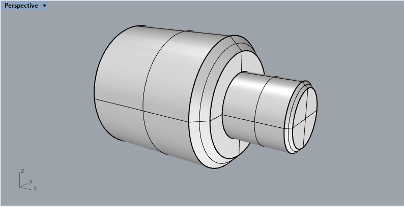
Ok so we have set up the initial tool starting point and given G71 all it’s needed settings. Now we have to tell the machine what we want made. So how about the shape below? Remember we are “drawing” the finished shape NOT doing a line by line construction.
First the machine needs to know what that P line is, and this is a bit weird, the Line Number is actually an N not a P so we start with
- N100 (this will be our P start point)
We are currently at X61.0 so that needs to change so we rapid to the smallest diameter on the end of our bar. In this case that is a diameter of 21mm so we go with
- N100 G00 X21.0
Now as we are at a diameter of 21mm and we are 3mm away from the end of the bar in free space. We don’t want to go screaming into the end of the bar at full noise so this should be a feedrate movement (Remember G01) so our next line is
- G01 Z0.0 (our F value or feed rate is already controlled by the F value in the second G71 line above so we don’t need to add it here)
So we are touching the end of the bar at 21mm and want to add that first chamfer. That will need both Axis to move at the same time. As we have already used G01 in the previous line we don’t need to add it again but for demonstration purpose I’ll put it in anyway)
- G01 X25.0 Z-2.0
We are now at a diameter of 25mm and 2mm into the job (the negative Z position) and we want to machine the 25mm long by 25mm diameter spigot so it’s a feed rate move again.
- G01 Z-25.0
Now we want to move to the bigger diameter and the start of the second Chamfer (this time a 5mm Chamfer)
- G01 X40.0
Holy shit, so far nothing has gone bang if you are paying attention. Now lets form that chamfer out to the 50mm diameter, so that’s a both axis move again.
- G01 X50.0 Z-30.0 (remember to cut a 45 degree chamfer what ever you move in X is half as much in Z, so a 5mm chamfer is 10mm on the diameter and 5mm on the length)
Now we just have to cut the 50mm diameter and finish off the length (again 50mm long)
- G01 Z-75.0
The last little bit is feeding up on the bar until we clear the actual bar but DO NOT exceed the X start position (in this case X61.0) Some Fanucs won’t worry if you exceed the size, others will error with “Sizes exceed material dimension” and some will just have a shit fit, pack all their toys and go f**king home) and as this is the last line of the shape we need that Q value (that’s is also a friggin N)
- N200 G01 X60.5
So what about we put that entire canned cycle together and see what we end up with?
- G00 X61.0 Z3.0
- G71 U2.0 R0.5
- G71 P100 Q200 U0.5 W0.0 F0.25
- N100 G00 X21.0
- G01 Z0.0
- G01 X25.0 Z-2.0
- G01 Z-25.0
- G01 X40.0
- G01 X50.0 Z-30.0
- G01 Z-75.0
- N200 G01 X60.5
That’s it, that is a G71 rough turning cycle, when you measure the sizes you will have a job that has 0.25mm of metal on the diameter to finish cut (your original U value on the second G71 line) and zero extra on the length (your original W value on the second G71 line) It’s gone from the original bar size to your roughed out size in 2.0mm steps.2.0mm steps being your first G71 line U value.
That’s really all these is to it, you can have all manner of shapes and weirdness that suits your needs on that diameter. There is one small caveat, older controls like 6T’s and similar cannot do Monal shapes, a Monal shape is when a position to the left is a smaller diameter than a position to the right (like a trombone shape) Later controls are fine with it but earlier versions will just go tilt and not run (some may try and just go bang).
So to recap the important shit,
- Check your data values (check twice, cut once is the rule)
- Don’t try and cut Monal shapes unless you know your control can do it.
- Don’t forget your line numbers (N values)
- Leave a nice big gap in those line numbers 100,200,300,400 etc, you may want to add more later for another cycle and line numbers can only appear ONCE in each program.
As G71 is also used for boring cycles there are some pieces of data that need to be changed in the cycle. Have a look at the G71 Boring page to see what we need to work with HERE
G71 Is A Canned Cycle